So you want to make an orrery?
There is something captivating about these devices that has made them endure for centuries past their inception, despite having had only the slightest scientific use in that time. I can only speculate that it’s the contrast of visually complex gearing and simple, and somewhat organic, motion that results from it. Whatever it may be, many enjoy these contraptions and if you’re here you may be considering design and/or fabricating your own. It may feel daunting when you think about all the complex parts and mechanisms all having to work together, but the wonderful thing is that you can make it as complicated or as simple as you’d like!
Want a simple demonstration model that’s visually accurate for a classroom or school project?
An inner planet orrery can be put together from little more than what is shown in the example below.
Looking for something a bit more involved?
A tellurion of the earth, moon, and sun involves compound rotations and illustrates solar days and eclipses.
Really looking for a project? Consider adding in other features to augment, expand, or refine your design:
Outer planets (now things are getting big!)
Motorized drivetrain
More complex drivetrains to drop errors down to <0.1%
Planetary axial tilts
*Planetary rotations
*Other moons (the four Galilean moons of Jupiter are a great choice)
**Even more complex drivetrains to drop errors to <0.001%
**Planetary eccentricity
**Nodal precession (planetary and/or lunar)
*These constitute an step up in complexity, as you’ll need to add high-speed rotation shafts to the orrery ‘trunk’ and gearing down the entire arm
**Another step in complexity, these features will only be found in the highest-end custom made orreries, namely Staines and Sons
Now that you know what’s possible … how do you design it?
Gearing
All that gearing seems pretty complicated, but in the end it’s almost all modular. You’ll have an input shaft (either hand-crank or motorized) rotating at a constant speed, and each planet will have a set of gears that translates that to its own orbital speed.
Let’s run through a simple Mercury, Venus, Earth example:
Determine how fast you want your orrery moving
A comfortable hand cranked input speed, say 60 RPM
Choose one planet and imagine how quickly you want it to orbit. Let’s say you want Earth to go around every 10 seconds. That means the orrery speed will be 0.1 year/second, or about 365/10 = 36.5 days per second.
This means for each rotation of the input the orrery is modelling 36.5 days elapsing.
Calculate the target gear ratios
Mercury has a year that is 88 days long, so we want a gear ratio of 36.5/88 = 0.415. For each rotation of the hand crank, Mercury orbits 0.415 orbits.
Venus has a year that is 225 days long, so we want a gear ratio of 36.5/225 = 0.162. For each rotation of the hand crank, Venus orbits 0.162 orbits.
Earth has a year that is 365 days long, so we want a gear ratio of 36.5/365 = 0.100. For each rotation of the hand crank, Earth orbits 0.100 orbits. Note that this is a very nice number because it’s what we used at the beginning.
Choosing Gear Ratios
But wait, how do I know what gear sizes to use to get those gear ratios? Excellent question, this isn’t something with a straightforward formula. There are few different methods and constraints to consider here:
Methods
Trial and error: just take two numbers and tweak them around until one divided by the other is close to your gear ratio.
Brute-force approach: Essentially runs through a list of possible gears and generates every combination and its resulting ratio, then finds the closest. If you’re up for a little programming (or even just excel) it’s a fun project. A simple way to algorithmically find good ratios. You can read more or download some MATLAB or excel files to calculate those here.
Stern–Brocot Tree: A more elegant, although more involved approach. Much more traditional and less computationally intensive, however will likely require some manual tweaking as well.
Use of #2 or #3 is recommended if you have more than a handful of gear trains to design.
Constraints
You’ll probably notice that there a multiple solutions depending on how close you want to get to the target value, how do you know which one to choose? A 3:7 gear set would give 0.429, is that good enough? Why wouldn’t you use 99:238 (0.416), shouldn’t that be better since its closer to the target of 0.415?
Minimum gear size: The first option would suggest a 3 tooth gear meshing to a 7 tooth gear. A rule of thumb is to not go below 10-12 teeth on any given gear. Why? The shape of the tooth actually changes based on how many teeth the gear has; as you get fewer and fewer teeth they become ‘undercut’ and weak, eventually not even being attached. An easy solution is to just multiply the tooth count on both gears! 15:35 gives the same result, but can actually be made
Maximum gear size: You might notice you can get closer to the target gear ratio more easily with high numbers. A 99 tooth gear meshed with a 238 tooth gear is very accurate, but both of these will be large gears. The diameter of the gear is proportional to the tooth-count, so this combination is more than six times larger than the previous option!
Error
You want to get close, but my advice is not to worry too much about this one. Can you tell the difference between something spinning at 60 RPM or 60.01 RPM? Likely not, so using a simple and small gear set is usually the best idea and nobody watching (including yourself) will be able to tell. You can see even with the simplest set of gears we can get accuracy of 0.1% on all three planets.
Co-axial Shafts
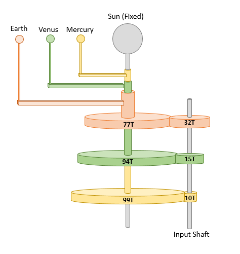
Looking at the first concept image below you may notice that the input gears (right side) don’t line up with each other. This will almost always be the case unfortunately, and can present a conundrum. How can you put all of them on the drive shaft if they don’t line up? Well… you can’t, but there are a couple ways to address this. The simple way is that you constrain the center-to-center distance of all three gear sets to be the same, which in effect means the sum of the tooth counts of each pair has to be the same. This will drop accuracy down quite a bit, but again keep in mind how accurate you need it to be. In our example this greatly simplifies the design and the motion error remains <1.5%.
Compound Gear Trains
Compound gear trains will let you get much higher resolution gear ratios and drop the error down correspondingly. They’ll gain you much flexibility, but get very complicated fast.
Initially selected gear sets for the example orrery. Note that it requires three independent input shafts.
Simple Option: Gear sets adjusted to permit a common input shaft. The sum of each gear pair is 109, and the errors are 0.14%, 1.50%, and 1.01% for Mercury, Venus, and Earth.
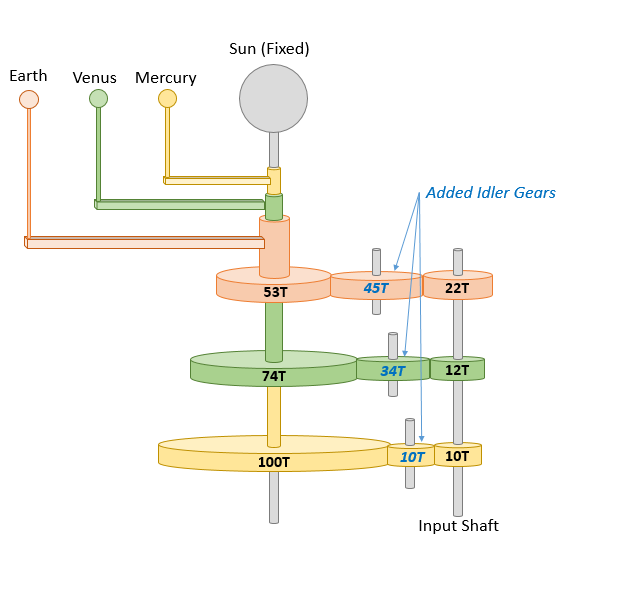
Complex Option: To retain the original accuracy, one can alternatively add ‘idler’ gears. The number of teeth doesn’t affect the actual gear ratio, so you have some flexibility to utilize. Here I’ve selected tooth counts that keep all the gears in a line for illustration.
Other Design Elements
Once you’ve got the gearing figured out there are a few other things that remain to have a complete design.
The Central Column
The most common design of orreries by far involves a series of nesting tubes down the central axis. The has been the popular design since they were first created and advances in machining have only made it more popular. For the everyday hobbyist an excellent start is a set of nesting brass tubes, which are readily available both at hardware stores as well as online. The very innermost is fixed and holds the sun, around it fits the Mercury tube, and then Venus, and so on. They will also need to be shorter as you go out so that each protrudes both from the bottom (for gearing) and top (for the arm) of the one around it. Beyond that
Integrated design, the gear is fixed to the tube and has groves machined into it to guide the rolling ball bearings. This design requires machined gears and will require the most tooling to construct, likely a 4-axis mill.
The design used in the coffee table orrery, each tube getting a brass disk soldered on that sits on a laser cut gear. A small pin installed in the gear fits into a slot in the disk to keep both pieces rotating together. This was a good solution for the tooling that was available to me at the time (manual mill+lathe and laser cutter)
An easier to produce design that avoids machining by splitting into the tube (stock material cut to length) and the gear (could be 3D printed or laser cut) and uses commonly available thrust bearings. The tube and gear will need to be glued, press-fit, or otherwise fixed together.
Planet Models
Likely the most artistic part of the orrery, as they only function to catch the eye. There is tremendous freedom as a result and many choose to make the planets contrasting to stand out. Planets can be made from stones, gems, or polished spheres for a more traditional aesthetic. More modern would be a 3d printed planet such as those offered by LittlePlanetFactory. Note that the three images shown are additionally using planetary rotation, an additional increase in complexity from a basic orrery.
Ivory Earth and Moon at the Cranbrook Institute Orrery
Painted globe Earth model (origin unknown)
3D printed sandstone Earth and Moon in Coffee Table Orrery
The Setting
You may also want to think about where to put your orrery. Is this a small clockwork unit for primarily display? Do you want it running continuously hanging from the ceiling as a mobile? Perhaps inside a coffee table with a glass top? Knowing this at the beginning is important to understand your size constraints, if you’ll need something protecting it from bumps or idle hands, or if if this is a long term project deserving of being a dedicated furniture piece.


